Physical terminations are the connectors, cabling, optics, and transceiver form factors that make the network real. They are often treated as simple parts until a link will not come up, runs at the wrong speed, has CRC errors, or fails after someone touches the patch panel.
Modern physical work includes copper categories, fiber type, connector polish, MPO polarity, optics compatibility, power budget, DOM readings, cleaning, labeling, and change control.
Connector Visuals
Use these as quick visual references. Real parts vary by vendor, boot style, latch, color, and generation.
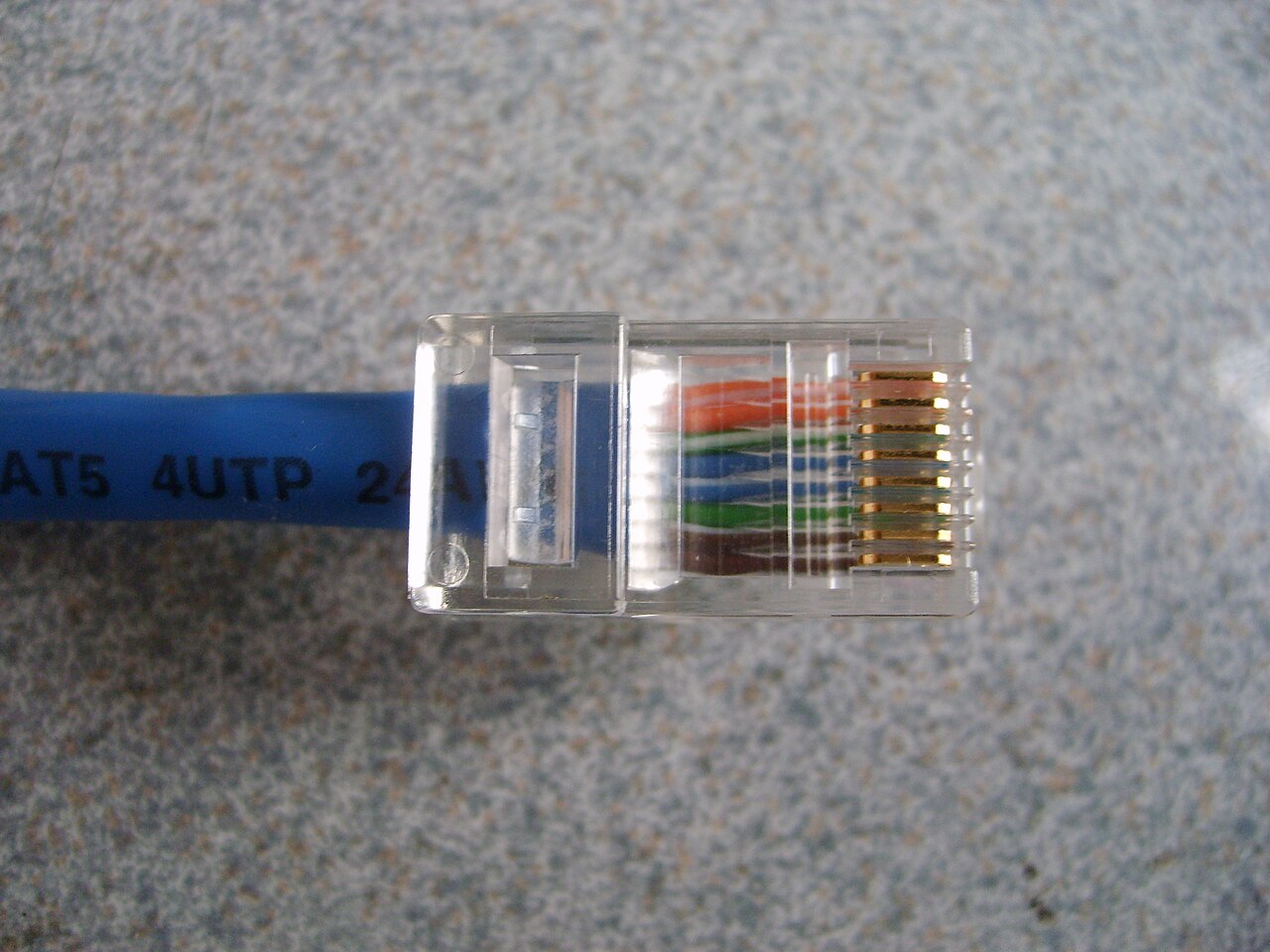
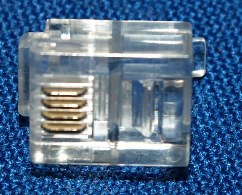
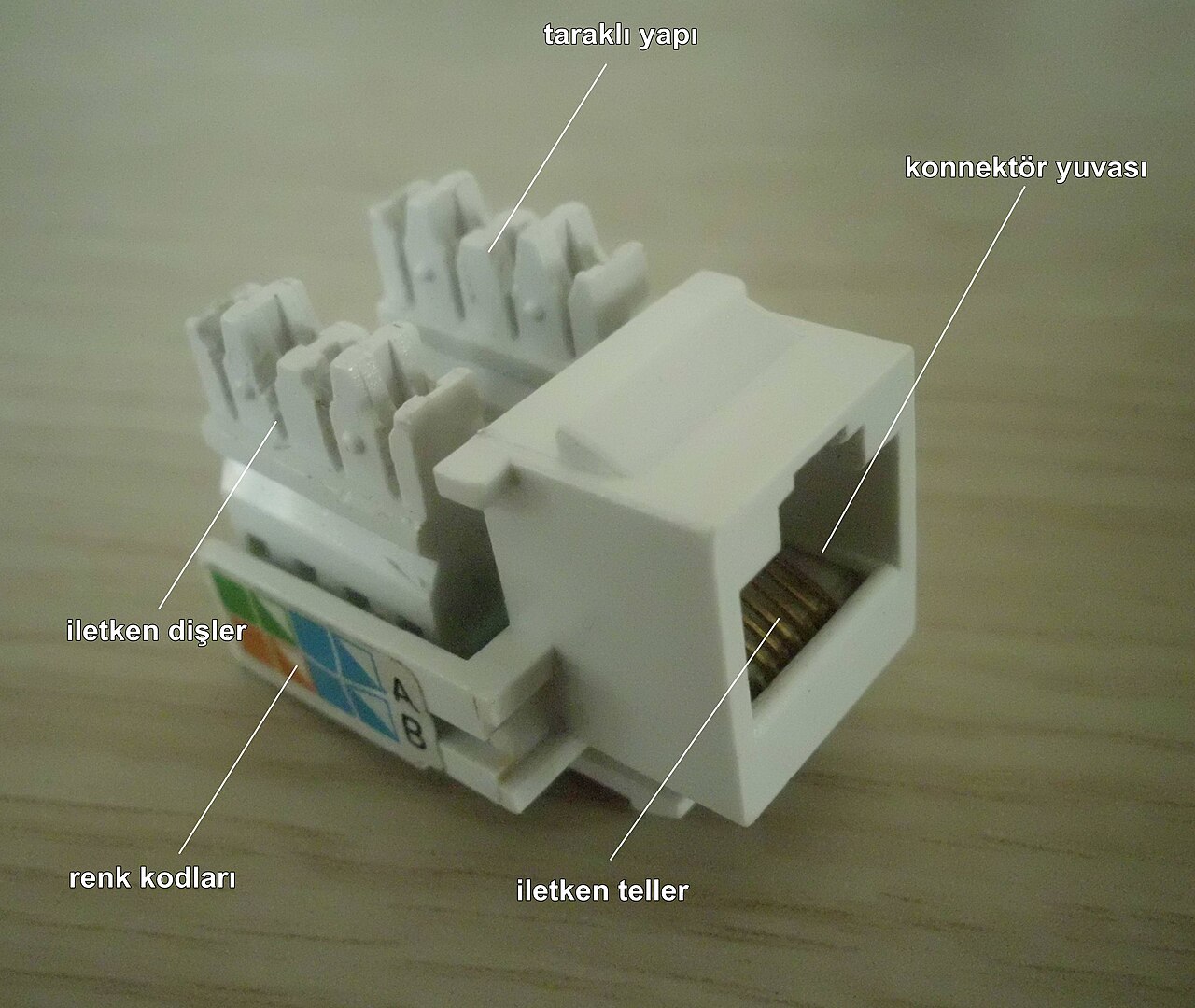
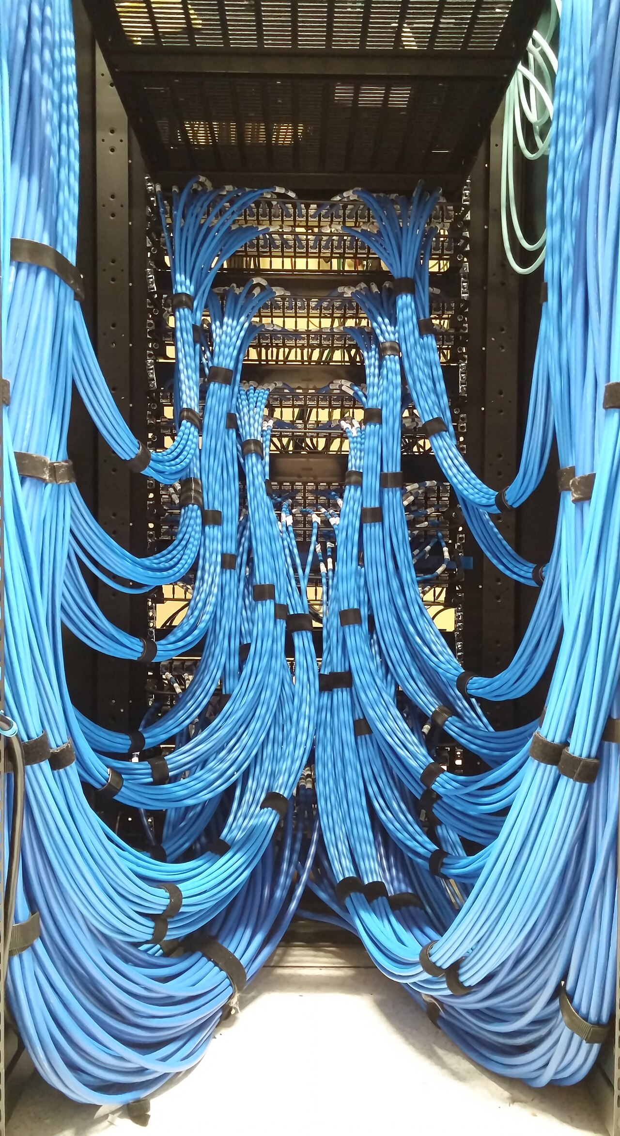
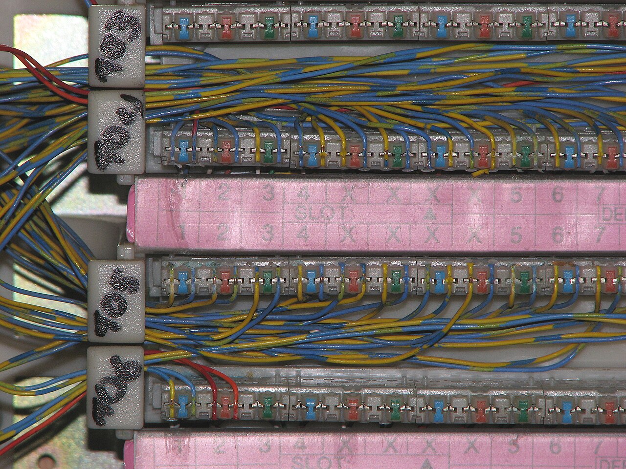
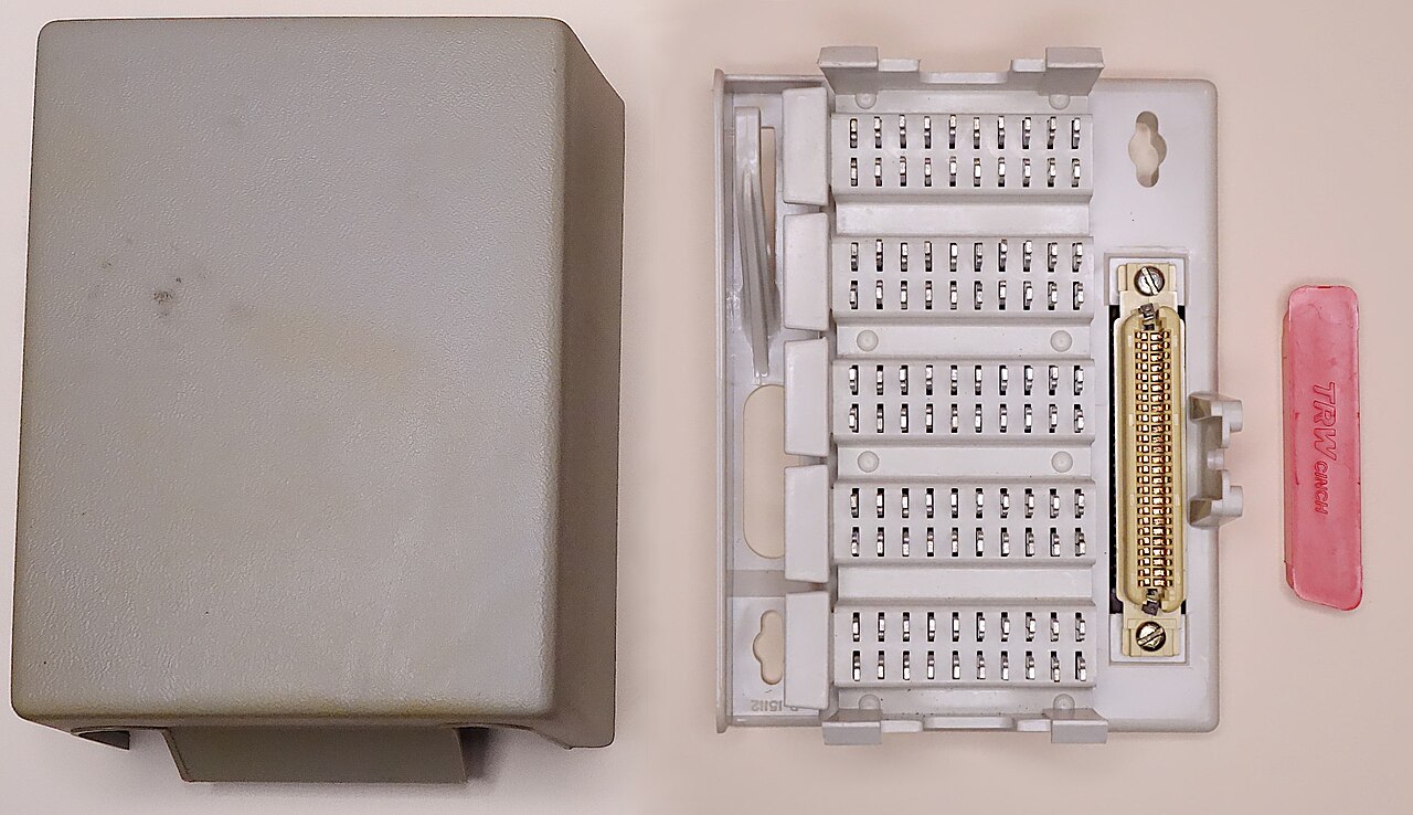
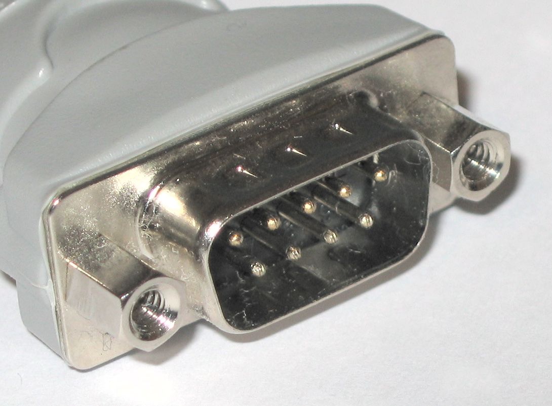
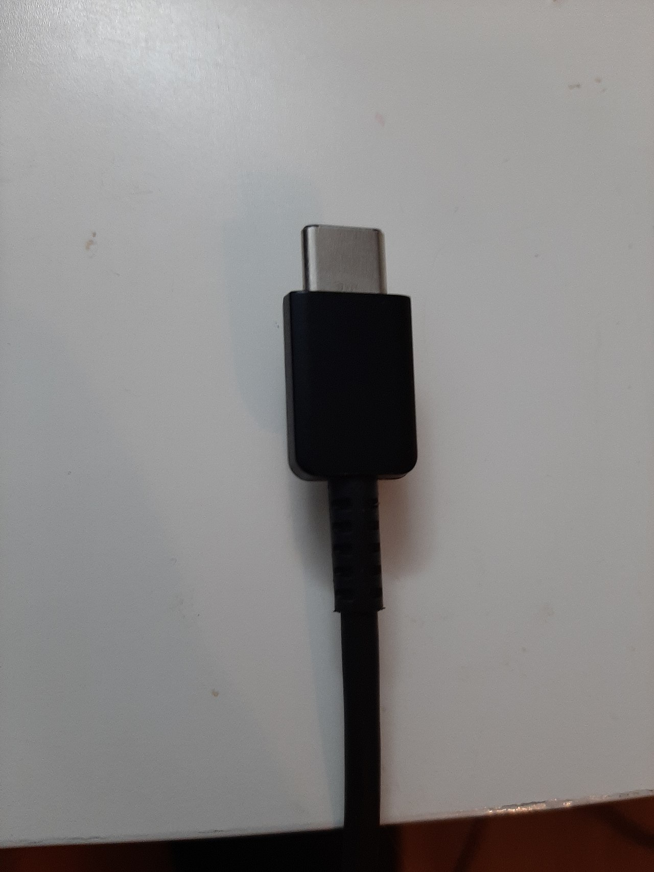
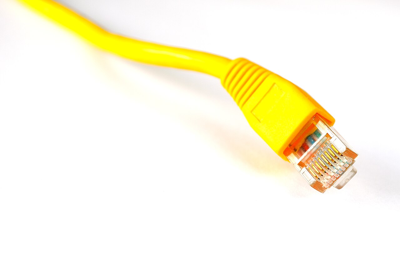
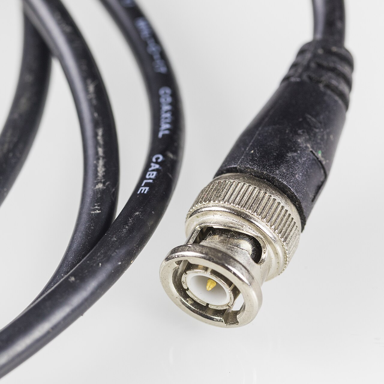
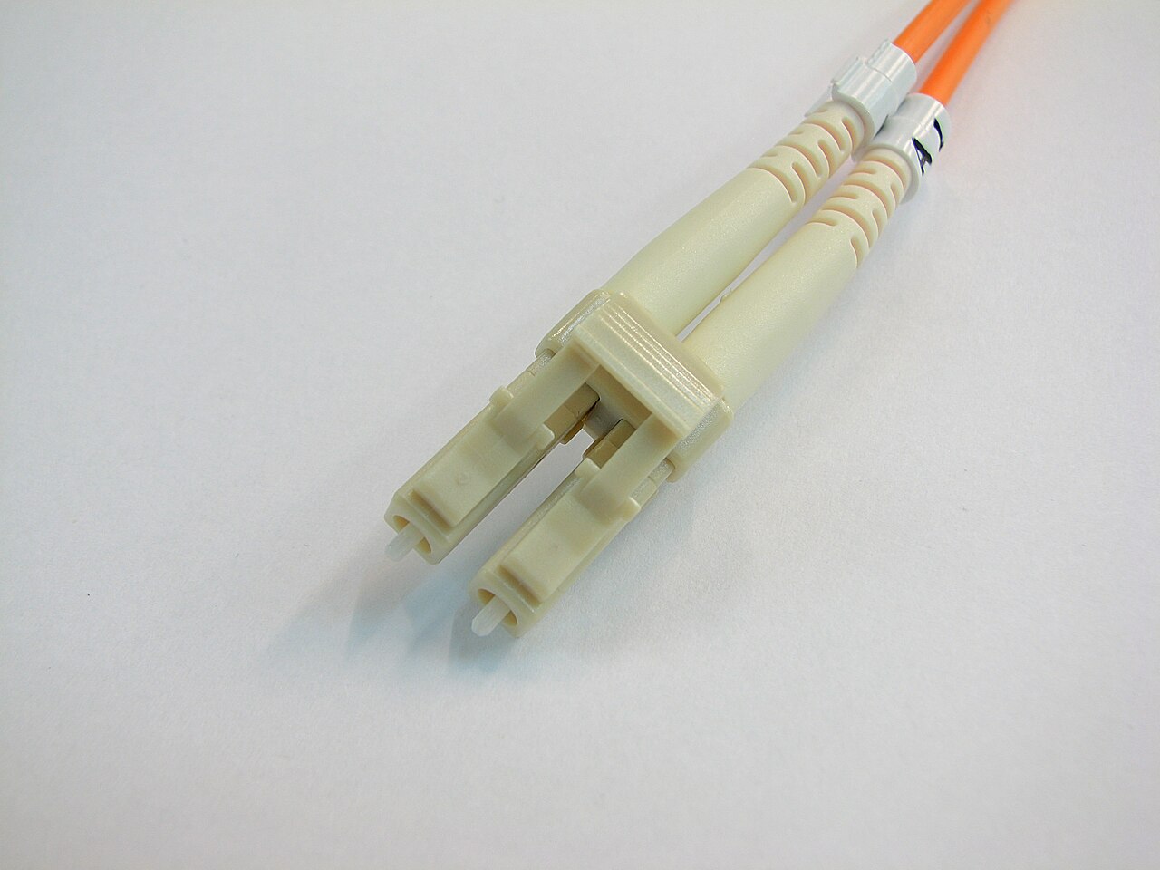
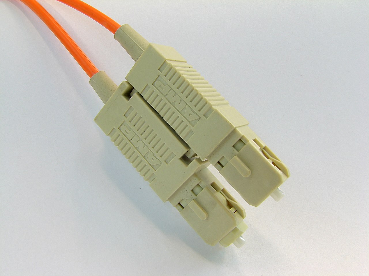
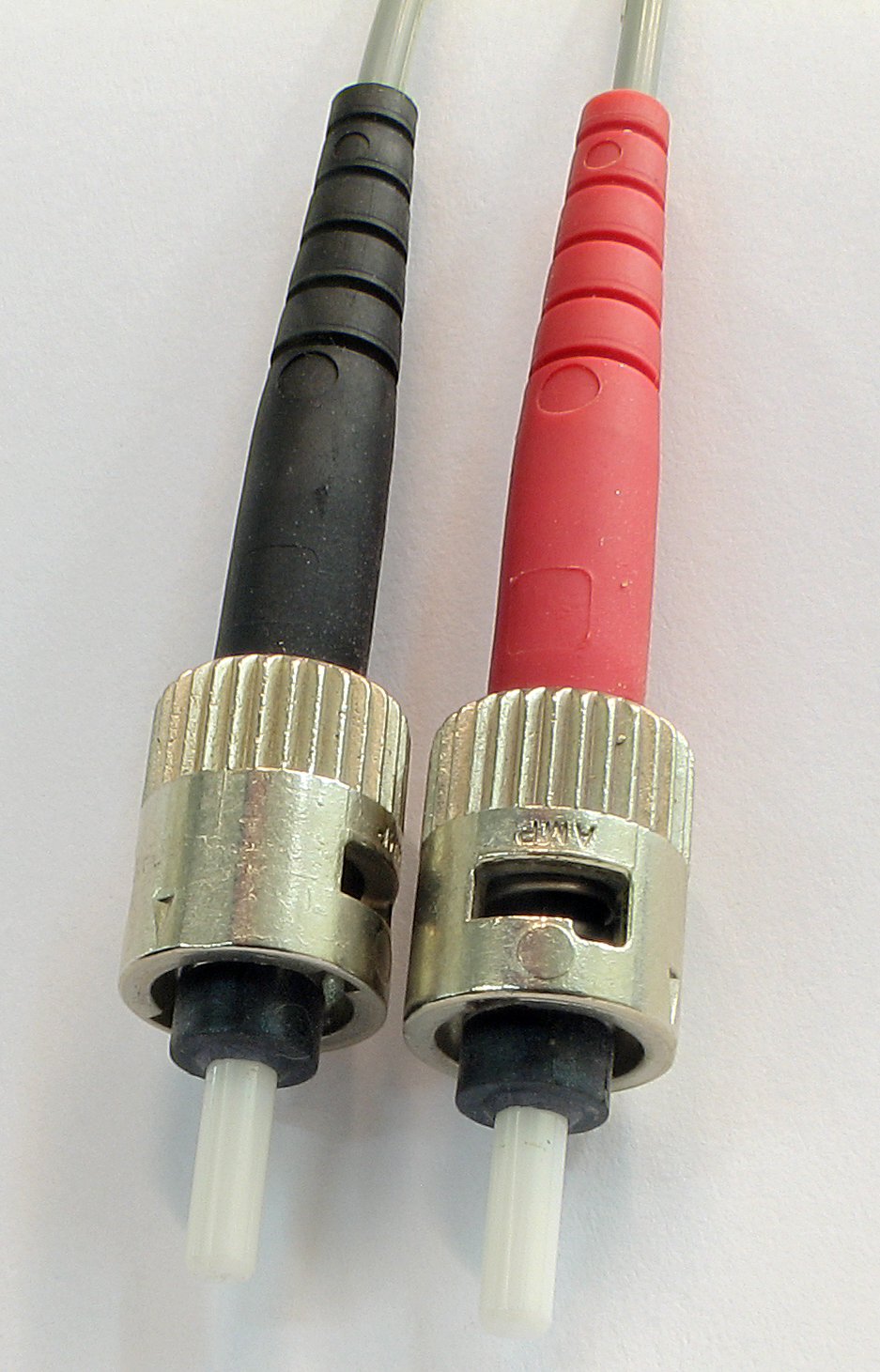
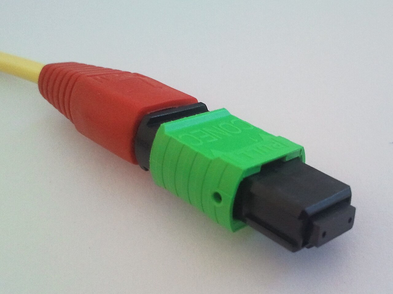
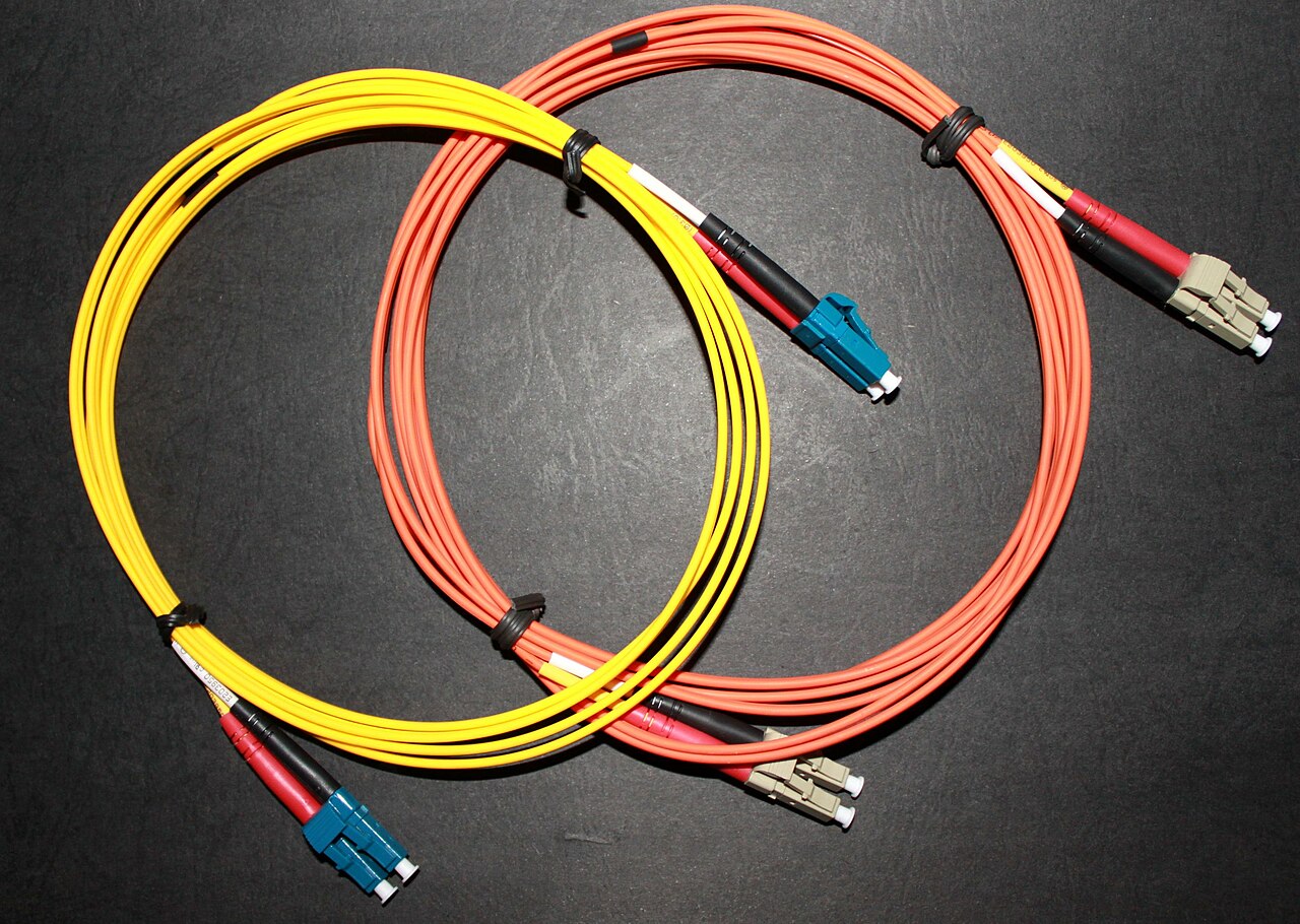
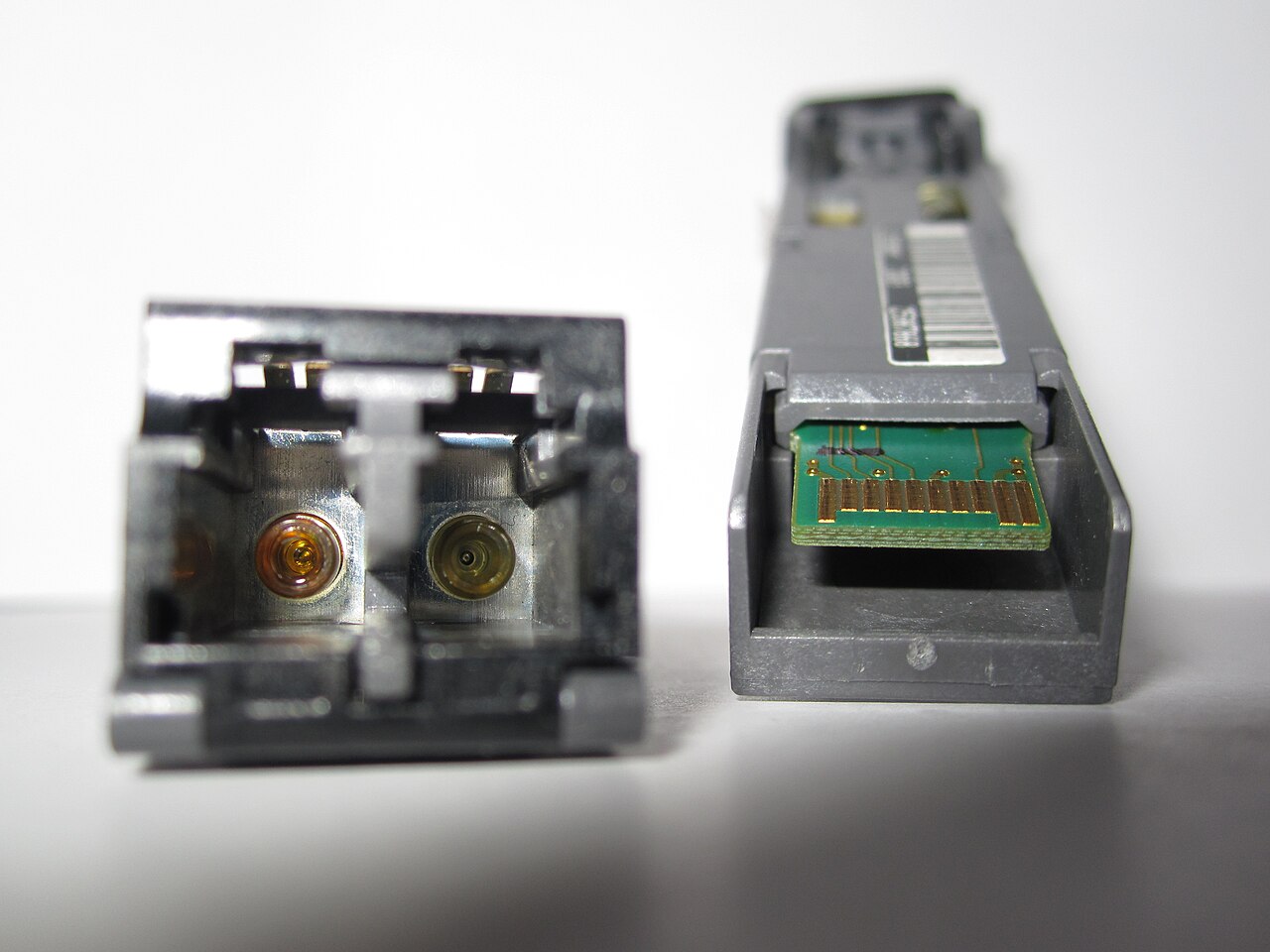
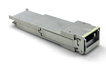
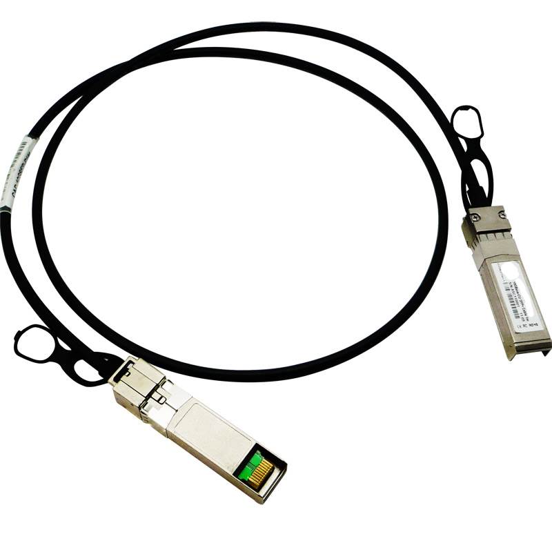
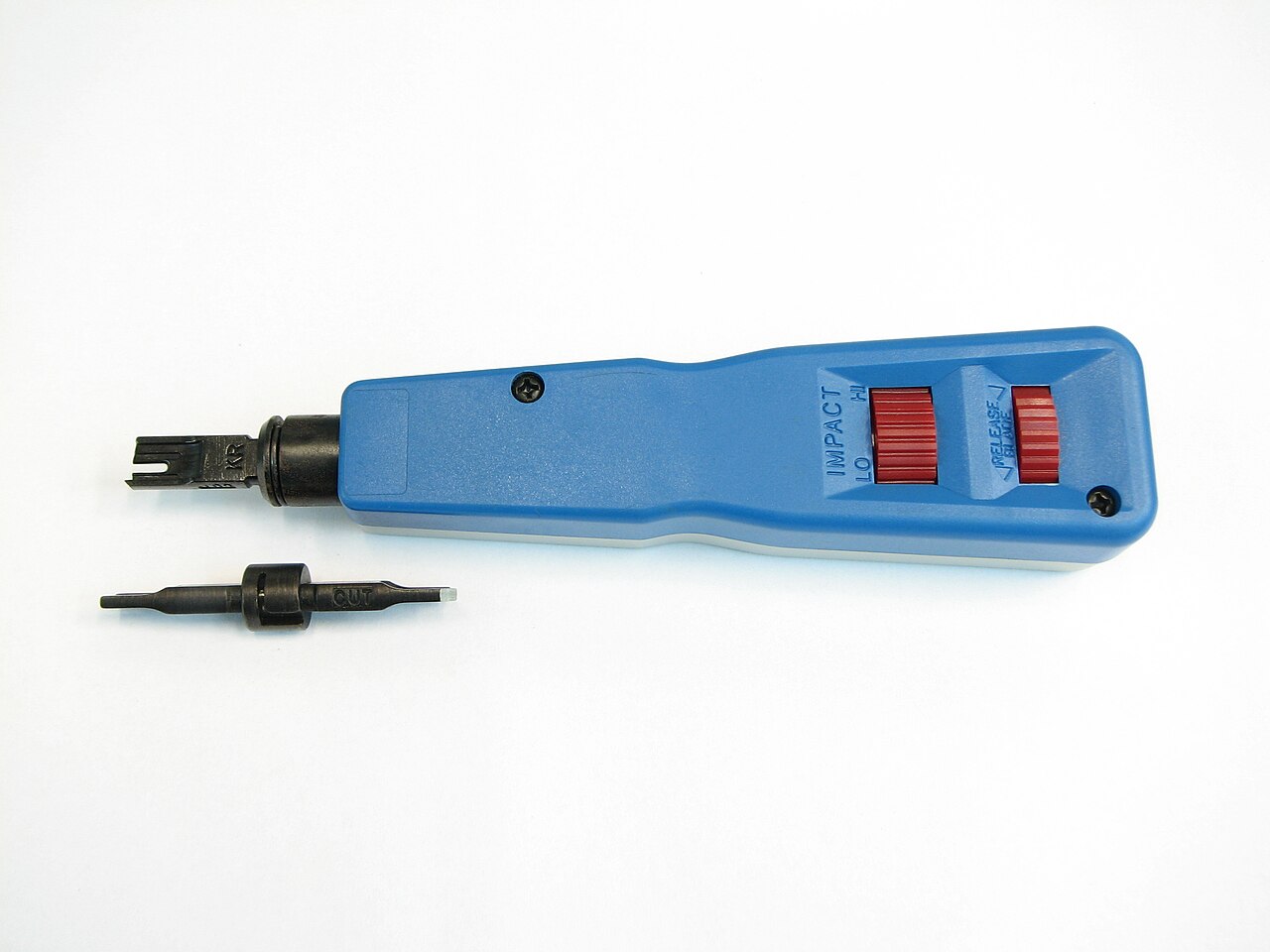
RJ-45 8P8C Ethernet plug endRJ-11 telephone-style plug endRJ-45 keystone jackEthernet patch panel110 punchdown blockRJ-21 or Amphenol 25-pair style telco blockDE-9 serial connectorUSB-C console connector endEthernet patch cableBNC coax connector for legacy Ethernet or videoLC duplex fiber connector pairSC fiber connector endST fiber connector endMPO or MTP multi-fiber connector endSingle-mode and multimode LC fiber jumpersSFP or SFP+ transceiver frontQSFP family transceiver frontDAC cable with fixed transceiver endsPunchdown tool
Copper
Connector
Common Use
Notes
RJ-45 8P8C
Ethernet twisted pair
Common access cabling
RJ-45 keystone jack
Wall plates, patch panels, modular inserts
Field-terminated structured cabling
RJ-11
Analog voice and DSL legacy
Smaller than RJ-45
RJ-21 / Amphenol
25-pair telco legacy
Voice blocks and older PBX systems
DE-9
Console and serial legacy
Often via USB adapter now
USB-C console
Modern device console
Increasingly common
BNC
Coax legacy Ethernet, video, test gear
Bayonet locking connector
Watch out: A cable can pass link but still fail under load because of pair quality, length, termination, or noise.
Copper Media
Media
Typical Use
Notes
Cat5e
1G access, sometimes 2.5G
Verify length and environment
Cat6
1G/2.5G/5G, short 10G
Common modern horizontal cable
Cat6A
10G to 100 m
Better alien crosstalk performance
DAC
Short rack connections
Passive or active twinax
AOC
Short to medium fiber-like runs
Active optical cable, fixed ends
Patch panel
Cable plant handoff in racks
Labeling and port maps matter
110 block
Voice and low-voltage punchdown
Mostly legacy for network data, still seen
Fiber Connectors
Connector
Common Use
Notes
LC
Most modern SFP/QSFP optics
Duplex or breakout
SC
Older patch panels and optics
Larger push-pull connector
ST
Legacy fiber
Bayonet style
MPO/MTP
High-density parallel optics
Polarity and pinning matter
Beginner Recognition Targets
Item
Why A New Networker Should Know It
RJ-45 plug vs RJ-45 jack
One is on the cable, one is mounted in a patch panel, wall plate, or device
Patch panel
Most office drops terminate here before being patched to switches
Keystone jack
Common field termination behind wall plates and patch panels
110 punchdown block
Common in older voice and structured cabling rooms
Punchdown tool
Seats copper conductors into IDC terminals
DE-9 serial
Older console and out-of-band management paths
USB-C console
Newer console connection on network devices
LC fiber
Default modern duplex fiber connector for many optics
SC and ST fiber
Older fiber plants and patch panels
MPO/MTP fiber
High-density 40G/100G/400G and breakout cabling
DAC vs AOC
Both have fixed module ends, but DAC is copper and AOC is active optical
Single-mode vs multimode jumpers
Jacket colors help, but always verify cable print and optic type
BNC coax
Legacy Ethernet, video, RF, and test environments
Modern note: Clean fiber before testing or inserting. Dirty connectors are a real outage cause.
Fiber Types
Type
Jacket Color Commonly Seen
Use
OS2 single-mode
Yellow
Long reach and most modern backbone
OM3 multimode
Aqua
Short reach 10G/40G/100G
OM4 multimode
Aqua or violet
Longer multimode reach than OM3
OM5 multimode
Lime green
Shortwave wavelength division use cases
Watch out: Jacket colors are helpful but not authoritative. Read the cable print and documentation.
Transceiver Form Factors
Form Factor
Common Use
SFP
1G
SFP+
10G
SFP28
25G
QSFP+
40G
QSFP28
100G
QSFP-DD
400G and beyond
OSFP
400G and beyond
Optic Families
Name
Media
Typical Meaning
SR
Multimode fiber
Short reach
LR
Single-mode fiber
Long reach
ER/ZR
Single-mode fiber
Extended reach
BiDi
Single strand pair
Uses different wavelengths each direction
CWDM/DWDM
Single-mode fiber
Wavelength multiplexing
T
Copper twisted pair
RJ-45 transceiver
Design note: Match speed, media, reach, wavelength, connector, breakout mode, and platform support. "It fits" is not enough.
Checks Before A Change
Check
Why It Matters
Platform support
Unsupported optics may err-disable or lack DOM
Speed and lane mode
4x10G, 4x25G, 1x100G, and breakout are not interchangeable
Fiber type
SMF and MMF optics are not interchangeable
Connector and polarity
MPO and duplex pairs can be reversed
Power budget
TX power, RX sensitivity, loss, and distance must fit
Cleaning
Dirt causes loss and reflection
Labeling
Saves the rollback
Cisco Commands
show interfaces status
show interfaces transceiver
show interfaces transceiver detail
show inventory
show logging | include TRANSCEIVER|SFP|GBIC|LINK
show controllers ethernet-controller <interface> phy
show interfaces <interface> counters errors
Expected clues:
Transceiver is recognized and supported.
DOM TX/RX levels are within expected range.
Speed and duplex match the design.
CRC, input errors, and link flaps are not increasing.
Interface description and patch labels agree.
Troubleshooting
Symptom
Check
Likely Cause
Link down
Admin state, optic support, fiber pair, speed
Wrong optic or reversed pair
Link flaps
DOM levels, dirty fiber, bend radius, errors
Marginal physical layer
CRC errors
Cable, patch, optics, speed, duplex
Bad copper or optical impairment
One side up only
TX/RX pair, wavelength, breakout mapping
Polarity or optic mismatch
DOM low RX
Loss budget, dirty connector, distance
Too much optical loss
100G breakout fails
Lane mapping, MPO polarity, platform mode
Wrong breakout or cabling
Watch Out
Do not look into fiber ends.
Do not clean fiber with random wipes or fingers.
Do not assume third-party optics behave the same across platforms.
Do not mix single-mode and multimode optics.
Do not skip labels on high-density MPO work.
Do not exceed bend radius just to make a rack look tidy.



_with_cover.jpg)


